


|
|
|||
|
|
|
|
|


| Frame should be boxed at least 4" on either side of the front frame bracket mounting area. | ||
| A | Center of holes in front frame bracket are located 2-1/4" behind the center of the top running board bracket mounting hole. Bracket is mounted flush with bottom of frame. |
|
| B | Rear axle brackets are located 41-5/8" apart measured from center to center at the coil-over mounting holes. Make sure that both brackets are the same distance from the end of the axle housing. Position the front face of the axle housing parallel to the back face of the axle brackets. Bars are assembled with adjusters at front. |
|
| Brackets should be tack welded and the assembly should be checked for square and alignment before final welding. | ||
| All welding should be performed by a qualified welder. | ||
| Please note - Kit is shown installed on our Model 'A' chassis with tubular crossmember and kick-up. All measurements also apply to stock Model 'A' chassis. Coil-over shocks and mounting hardware are optional. |
||


| Frame should be boxed at least 4" on either side of the front frame bracket mounting area. | ||
| A | Center of hole in front frame bracket is located 2-1/4" behind the center of the top running board bracket mounting hole. Bracket is mounted flush with bottom of frame. | |
| B | Rear axle brackets are located 38" apart measured from center to center at the coil-over mounting holes. Make sure that both brackets are the same distance from the end of the axis housing. Position the front face of the axle housing parallel to the back face of the axle brackets. Bars are assembled with adjusters at front. |
|
| C | install angle brackets on adjuster end of short bar and housing tabs on opposite end. Housing tabs are located 15" from center to center. Angle brackets may require slight trimming for correct fit. Check for floor pan clearance before final welding. | |
| Brackets should be tack welded and the assembly should be checked for square and alignment before final welding. | ||
| All welding should be performed by a qualified welder. | ||
| Please note - Kit is shown installed on our Model 'A' chassis with tubular crossmember and kick-up. All measurements also apply to stock Model 'A' chassis. Coil-over shocks and mounting hardware are optional. |
||


| Frame should be boxed at least 4" on either side of the front frame bracket mounting area. | ||
| A | Center of lower bolt hole on front bracket is located 8-1/4" forward from the center of the lower fender mounting hole. Frame bracket is positioned on inside of boxed frame rail flush with the bottom with the ears facing up. Frame brackets may need slight trimming to fit flush. | |
| B | Rear axis brackets are located 36" apart measured from center to center at the coil-over mounting holes. Make sure that both brackets are the same distance from the and of the axle housing. Position the front face of the axis housing parallel to the back face of the axle brackets. | |
| C | Center of axle housing is positioned 27-1/2" forward from center of the rear spreader bar hole. Check to be sure housing is centered in wheal well before final welding. | |
| Bars are assembled with adjusters at front | ||
| Brackets should be tack welded and the assembly should be checked for square and alignment before final welding. All welding should be performed by a qualified welder. | ||

| A | Center of hole in front bracket is located 30-1/2" forward of axis housing center. Bracket is positioned on inside of boxed frame rail flush with the bottom with the ears facing up. Frame brackets may need slight trimming to fit flush. | |
| B | Rear axle brackets are located 38" apart measured from center to cents at the coil-over mounting holes. Make sure that both brackets are the same distance from the end of the axle housing. Position the front face of the axle housing parallel to the back face of the axle brackets | |
| C | Install angle brackets on adjuster end of short bar and housing tabs on opposite end. Housing tabs are located 16-1/2" from center to center. Angle brackets may require slight trimming for correct fit. Check for floor pan clearance before final welding. | |
| Coil-Over shocks and mounting hardware are optional | ||
| Bars are assembled with adjusters at front | ||
| Brackets should be tack welded and the assembly should be checked for square and alignment before final welding. All welding should be performed by a qualified welder. | ||


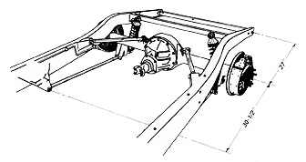
| A | Center of rear axis housing is located 18" back from the center of the fender mounting hole indicated. | |
| B | Rear axis brackets are located 37" apart measured from center to center at the coil-over mounting holes. Make sure that both brackets are the same distance from the end of the axle housing. Set pinion angle before welding brackets to housing. Brackets should be mounted parallel to the upper shock mount to eliminate bind on shocks. | |
| C | Frame brackets slip into x-member. Install bars to properly position the frame brackets at the correct angle. Brackets may require minor trimming for correct fit. | |
| Bars are assembled with adjusters at front | ||
| Brackets should be tack welded and the assembly should be checked for square and alignment before final welding. All welding should be performed by a qualified welder. | ||
| Coil-Over shocks and mounting hardware are optional | ||
|
|
|
|
|
| All Prices subject to change without notice. |
Last Updated:
|
||
| Copyright © 2000-2003 - Zig's Street Rod Center Inc. | |||